
Karst topography in limestone forms as a result of dissolution of calcium carbonate by rainwater. There are vast limestone pavements of these structures in the Jebel Shams area of Oman (Fig. 1). There is a distinctive pattern of blocks surrounded by joints/fractures (Fig. 2). The solution enhanced fractures are often called grykes and the blocks called clints.

Figure 1. Karst topography in Jebel Shams, Oman.

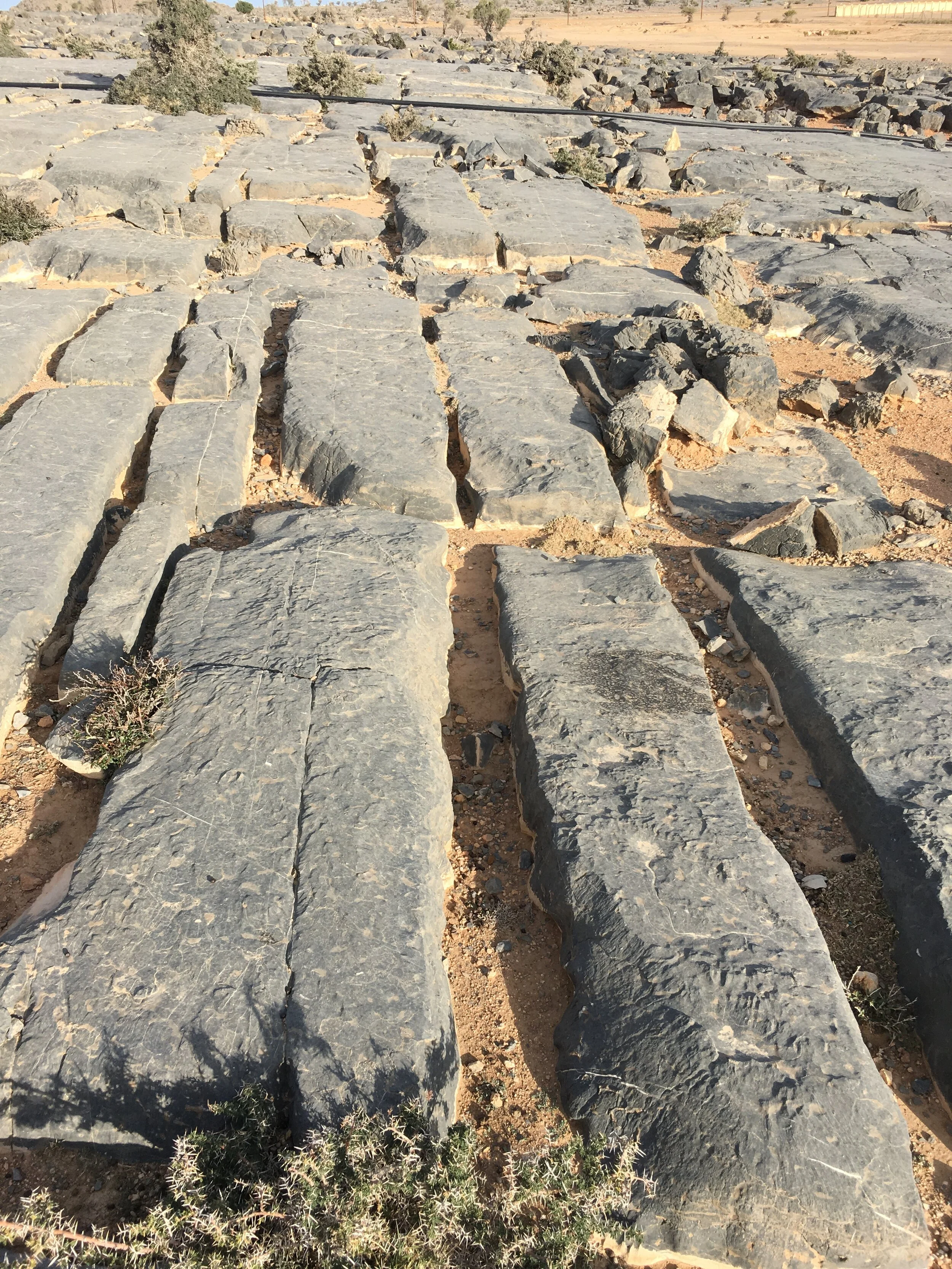
Figure 2. Karst-related fractures in Limestone, Jebel Shams, Oman. Note the sheet-like matrix blocks, numerous calcite veins, shells and slickenlines.
Note that the blocks are rectangular in shape so we can use a simple sheet model (Fig. 3) to derive fracture porosity and permeability.
The fracture aperture in the subsurface should be a lot less but even the 0.2 mm that I used here is a bit on the small side. Anyway, it’s just to illustrate the calculation. So, using the nomograph for the sheet model on Fig. 4 and 0.2 mm aperture, a spacing width of 6 m we get a porosity of 0.003 % and a permeability of 0.1 D.
We get the same porosity result if we simply divide aperture by spacing and multiply by 100 (working in cm):
Fracture porosity = aperture/spacing * 100
= 0.02/600*100 = 0.003 %.
In conclusion, a simple sheet model can be used to relate fracture aperture to spacing/width, porosity and permeability when the matrix blocks are rectangular - as is often the case with regional fractures.
There’s really no need to build a computer model to derive the fracture porosity and permeability - and an uncertainty range can be put together by varying the aperture and spacing. Reiss (1980) has provided nomographs for other models such as matchsticks, cubes with 1 ineffective fracture direction and cubes (cases B - C in Fig. 3).

Figure 3. Four geometrical relationships between matrix blocks and the fractures that separate them: A) sheets, B) match sticks, C) cubes with one ineffective fracture plane, D) cubes. Reiss (1980).

Figure 4. Nomograph (Reiss, 1980) for the sheet model in Fig. 3 which relates fracture porosity, permeability, spacing and aperture.
Reference
Reiss, L.H. 1980. The reservoir engineering aspects of fractured formations.