

How to identify natural fractures in rock core.
Here’s some rules I follow when identifying natural fractures (i.e. not induced by coring or core handling) in the core store.
Top of the list is fracture cement i.e., minerals that have been precipitated out from fluids travelling through the fracture - Fig. 1.
Deformation bands which may look like veins (cement) but are made up of crushed sand grains - Fig 2. This includes other fault rock processes like clay smear.
http://www.ogilviegeoscience.co.uk/blog/2022/11/24/deformation-bands-bad-news-for-your-reservoir-
Displacement /cross-cutting of beds or older fractures - Fig 2b.
Slickenlines/polished surfaces on fracture faces - these are scratches from the shear movement of opposing walls and are therefore indicators of natural shear fractures - Fig. 3.
http://www.ogilviegeoscience.co.uk/blog/2022/11/29/importance-of-slickenlines-on-a-fault-surface
Fractures that are confined to beds/layers or certain lithologies i.e., mechanical stratigraphy.
Stylolites form as a result of pressure solution which dissolves the rock - Fig. 4.
Enclosed within the core - both ends of the fracture terminate within the core stick - Fig. 5.

Fig. 1 Fracture cements (a) Pyrite cemented fractures in sandstone, West of Shetland, UK. (b) Barite cemented fractures in fine grained (Rotliegende) sandstones, Vanguard Field, Southern North Sea.

Fig. 2 Deformation bands in Rotliegende sandstones from Southern North Sea. (a) White coloured deformation bands cross cutting bedding (b) Deformation bands that become more prominent close to a seismic scale fault (from left to right). Bedding displacement as a shear indicator - some examples circled. From S Valiant Field, Southern North Sea.

Fig. 3. (a) Slickenlines on a fault surface in mudstone core, North Sea, UK. (b) polished surface in Lower Cretaceous (Albian) sandstones from Central North Sea. http://www.ogilviegeoscience.co.uk/blog/2022/11/29/importance-of-slickenlines-on-a-fault-surface
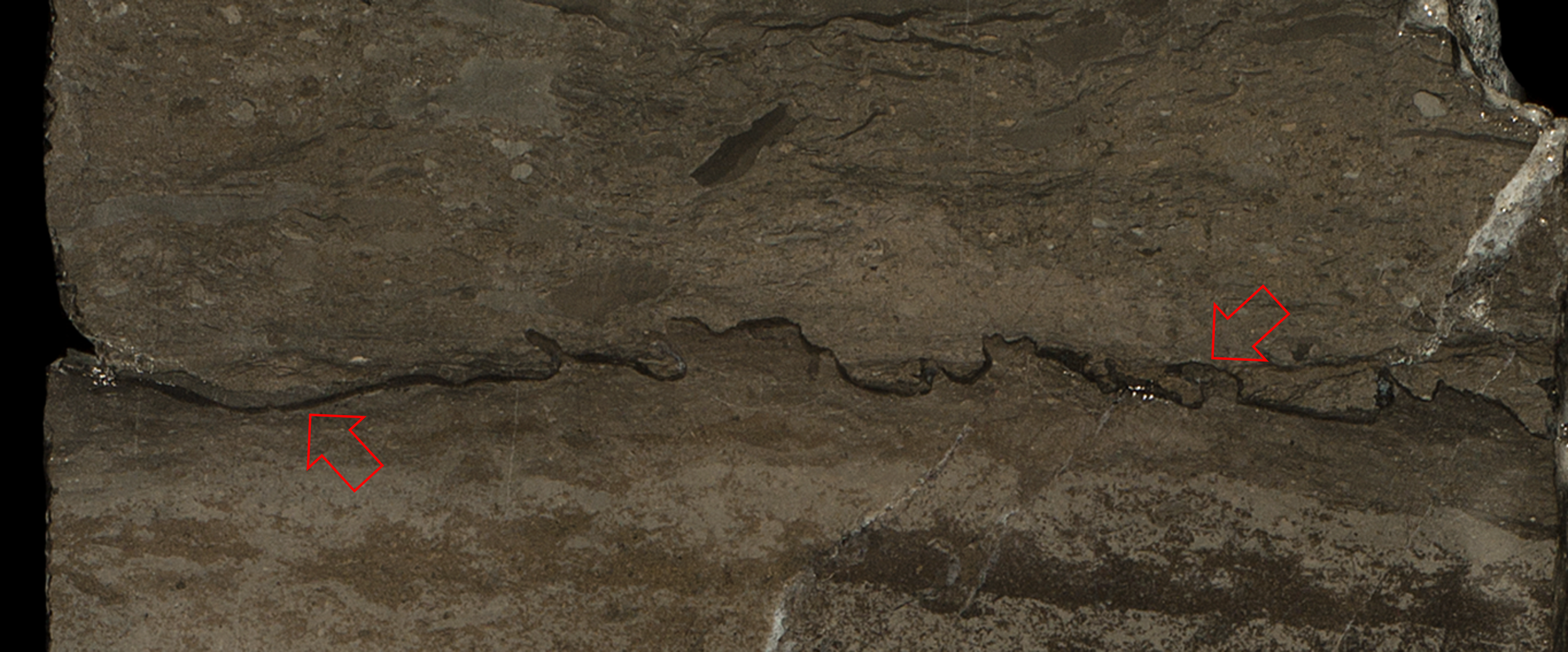
Fig. 4. Stylolite in limestone core from Middle East - running from left to right parallel to bedding.

Fig. 5. Open fractures towards the base of this dolomite core piece (circled in red) are likely natural as they terminate within the core.
And what about induced fractures ?
Induced fractures are often called hydraulic fractures (Fig. 6a) if the intention is to create fractures to stimulate production - otherwise they are just induced fractures e.g., through careless core handling. See refs [1 - 2] for a detailed discussion.
In addition to not having the above features, induced fractures [1] tend to be
Irregular or conchoidal [2] particularly in fine grained rocks.
Centerline fractures - during drilling - an extension fracture propagated in front of the coring/drilling bit due to the weight of the drill string. The fracture often appears in the centre of the core hence the name [1]
Petal fractures [1,2] - due to frictional stick-slip between core and core bit - well spaced fractures either side of the core - they can intersect from opposite sides of the core creating unusual shapes - the fractures often propagate down the core as centerline fractures - Fig 6b.
Bedding parallel fractures - more of these get created with increased handling [3]. Flexing of core boxes/rough transportation also a factor especially in shale core [2] - Fig 6c.
BUT bedding planes can become reactivated as fractures in which case look out for slickenlines, polished surfaces and cements - for evidence of natural fractures.
Helical/spiral fractures due to core breakage during coring - due to twisting or torque applied to the core from the core bit or core barrel [2].
Desiccation fractures due to core drying, in shale cores - Fig 6c (right)
Rubble - often through poor core handling/transportation - BUT often rock gets broken up because the well has been drilled through a geological fault zone - those in Fig 7 are natural (hairline) fractures (from a fault zone) that surround pods of mudstone- the pods have become dislodged during coring.

Figure 6. Induced fractures in core (a) hydraulic fractures with large apertures, parallel to core axis (b) petal fractures, (c) bed parallel fractures in mudstone with further fractures created due to drying (once in core store) in right hand stick.

Figure 7. Rubble zone in mudstone (North Sea) where well has penetrated a seismic scale fault. The rubble has been created during drilling which has broken up pods of mudstone surrounded by natural fractures. Each tray is 1 metre long.
References
[1] Kulander, B.R., Dean, S.J., Ward, B.J. 1990. Fractured core analysis. Interpretation, Logging, and Use of Natural and Induced Fractures in Core. AAPG Methods in Exploration Series, No. 8.
[2] Determining Natural Vs Induced Fractures (p230) in - Nelson, R.A. Geological Analysis of Naturally Fractured Resevoirs. Determining Natural Vs Induced Fractures.
[3] Reiss, L.H. 1980. The Reservoir Engineering Aspects of Fractured Formations. Gulf Publ. Co. 107 pp.